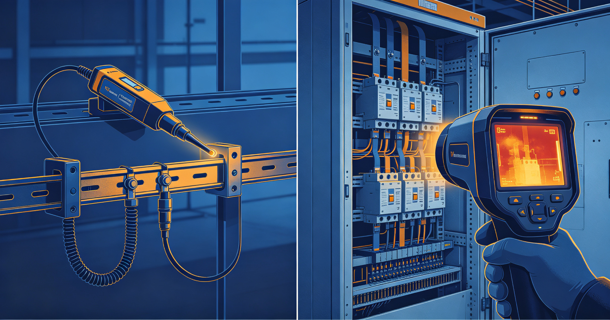
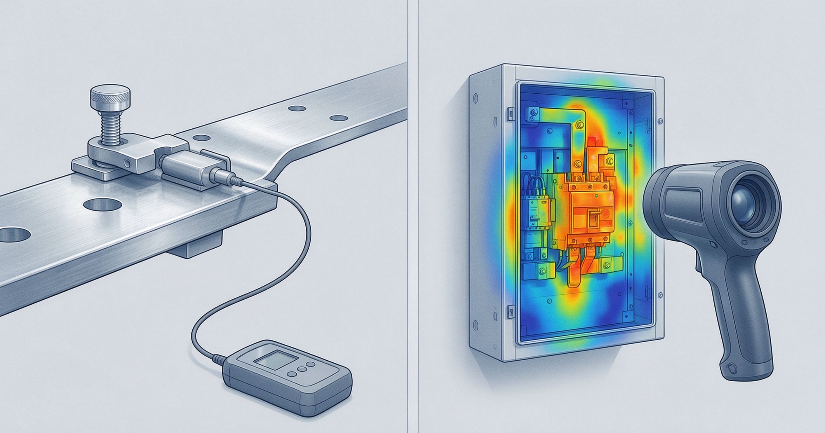
Illustration: Contact Temperature Sensors vs Infrared Thermal Imaging for Switchgear Monitoring
For most switchgear installations, contact sensors win on accuracy and cost when you can access the bus bars during a planned outage. Infrared thermal imaging wins when you need to survey energized equipment without downtime. The two methods measure different things: one reads surface temperature directly, the other infers it from radiated energy. Choose based on access, budget, and whether you need continuous or periodic data.
How Each Method Actually Works
Contact temperature sensors — typically resistance temperature detectors (RTDs), thermocouples, or fiber-optic probes — mount directly on or inside the conductor, bus bar, or termination. They output a signal proportional to the physical temperature of the surface they touch. A Class A PT100 RTD, for example, holds an accuracy of ±0.15 °C at 0 °C and ±0.35 °C at 100 °C per IEC 60751. That is the temperature of the metal, not a guess.
Infrared thermal imaging works differently. A thermal camera detects radiated infrared energy in the 7–14 µm band and converts it to a temperature reading using the target's emissivity. For oxidized copper bus bars, emissivity typically sits between 0.6 and 0.8. For shiny aluminum, it can drop to 0.05–0.2. Get that number wrong and your reading can be off by tens of degrees. NFPA 70B (2023 edition) acknowledges this and requires documented emissivity correction when using IR for predictive maintenance.
The measurement target also differs. An IR camera sees the surface it is pointed at. A contact sensor reads the point it is bonded to. On a bolted joint with a hidden hot spot behind the bolt head, IR may miss the fault entirely while a contact sensor bonded to the bar catches it.
Comparison Table
| Criterion | Contact Sensors | Infrared Thermal Imaging |
|---|---|---|
| Typical accuracy | ±0.5 °C or better (RTD/fiber) | ±2 °C or ±2% of reading (camera-dependent) |
| Measurement type | Direct, point measurement | Indirect, surface radiance |
| Emissivity dependency | None | High — corrections required |
| Access requirement | Physical contact, often during outage | Line-of-sight only, works energized |
| Coverage | Only instrumented points | Full field of view per image |
| Continuous monitoring | Yes — 24/7 data stream | No — periodic snapshots |
| Typical installed cost per point | $150–$600 (sensor + wiring + install) | $0 per point (survey labor only) |
| Labor model | One-time install, low recurring | Recurring survey cost, 1–4 visits/year |
| Detects hidden faults | Yes, if bonded to the right spot | No — blocked by covers, glass, or geometry |
| Arc-flash exposure during use | None after install | Present during survey |
| Best for | Critical joints, remote assets, trend data | Broad periodic inspection, troubleshooting |
Where Contact Sensors Outperform
Fiber-optic and RTD sensors shine in three situations: continuous monitoring, hard-to-reach equipment, and any location where emissivity is unpredictable.
Continuous data and early fault detection
Switchgear faults rarely appear overnight. A loose bolted connection may creep from 65 °C to 90 °C over weeks as contact resistance rises. A contact sensor polling every 10 seconds catches that slope. An annual IR survey catches it only if the survey happens to fall on the right week. For critical assets — main breakers, generator connections, transformer terminations — continuous data changes the maintenance model from reactive to predictive. Early warning solutions such as Chilion's ICOP can flag a 5 °C rise above baseline before it approaches the 90 °C threshold that many operators treat as the action limit for bare copper connections.
Sealed and enclosed equipment
Metal-clad switchgear, GIS compartments, and oil-filled transformers block infrared radiation. IR windows are available, but they add cost, introduce a viewing angle limit, and still cannot see around internal obstructions. A fiber-optic sensor bonded to the bus bar inside a sealed compartment reads temperature regardless of what is in the way.
Emissivity-challenged surfaces
Polished aluminum bus bars, tinned copper with fresh plating, and any surface with a low, unstable emissivity are poor IR targets. ASTM E1933 and ISO 18434-1 both cover emissivity measurement and correction procedures, but in practice the correction is often skipped or approximated. Contact sensors sidestep the problem entirely.
Where Infrared Thermal Imaging Outperforms
IR wins on speed, coverage, and capital cost — three things that matter a great deal in the field.
No downtime, no installation
A thermographer can survey a 50-section switchgear lineup in a few hours without de-energizing anything. Contact sensors require a planned outage to install, plus routing for signal wiring and a monitoring gateway. For facilities where downtime costs more than the survey itself, IR is the practical choice.
Broad coverage per visit
One thermal image captures hundreds of joints at once. You see the whole lineup, not just the points you instrumented. That breadth catches anomalies you would not have thought to monitor — a failing breaker contact, a misaligned bus splice, a hot lug on an unrelated feeder.
Lower entry cost
A mid-range thermal camera for electrical inspection runs $3,000–$12,000. A contact sensor system across 40 joints runs $10,000–$25,000 once you include sensors, wiring, gateway, and commissioning. For smaller facilities, IR is often the only economically viable option.
Troubleshooting and root-cause work
When a breaker trips or a fuse blows, IR quickly shows what is hot and what is not. That diagnostic strength is hard to replicate with point sensors, which only report on the points you already suspected.
Standards and Compliance Considerations
Both methods appear in recognized standards, and neither is universally mandated for switchgear monitoring.
- NFPA 70B (2023) — Recommends infrared inspection as part of a preventive maintenance program and requires documented emissivity correction. It also recognizes continuous temperature monitoring as an acceptable alternative for inaccessible equipment.
- IEC 62271-1 — Specifies temperature-rise limits for switchgear (e.g., 75 K rise for bare copper connections, 65 K for tinned). Contact sensors measure against these limits directly; IR must be corrected for emissivity first.
- ISO 18434-1 — Governs condition monitoring and diagnostics of machines using thermography, including emissivity and reflected-apparent-temperature correction.
- ASTM E1933 — Standard test methods for measuring and compensating for emissivity when using IR imaging radiometers.
- UL 2735 and IEEE C37.20.2 — Address temperature monitoring and metal-clad switchgear construction, relevant when specifying either method.
A 2021 study in IEEE Transactions on Industry Applications found that emissivity errors of 0.2 on a copper target at 80 °C produced apparent temperature deviations exceeding 15 °C. That is enough to mask a developing fault or trigger a false alarm.
For a broader look at how monitoring fits into a facility safety program, see electrical safety program basics.
Recommendation by Use Case
There is no universal winner. The right choice depends on what you are protecting and what constraints you face.
Choose contact sensors when:
- The asset is critical and unplanned downtime is expensive (main switchgear, data center feeds, generator interconnects).
- The equipment is sealed, enclosed, or has limited line-of-sight access.
- Surfaces have low or unstable emissivity.
- You need trend data and automated alarms, not periodic snapshots.
- You have a planned outage window for installation.
Choose infrared thermal imaging when:
- You need broad inspection coverage across many assets with limited budget.
- Downtime is not available or not justified.
- You are troubleshooting an active fault or verifying a repair.
- The facility is small or medium-sized with a manageable number of critical joints.
- You already employ certified thermographers (Level I or II per ASNT or ISO 18436-7).
Use both when:
The strongest programs combine a periodic IR survey for broad coverage with continuous contact monitoring on the 10–20 highest-risk joints. The IR survey catches the unexpected; the contact sensors catch the slow drift between surveys. For a related comparison of detection methods, see arc flash detection methods.
For guidance on how temperature thresholds translate into maintenance actions, refer to temperature rise limits in switchgear.
Need a passive fire protection assessment?
Our editorial team covers enclosure fire suppression, electrical safety monitoring, and fire-resistant coatings. Talk to our partners about your specific application.
Frequently Asked Questions
Can infrared thermal imaging replace contact sensors entirely?
No. IR cannot see inside sealed compartments, is limited by emissivity error, and provides only periodic snapshots. For critical assets requiring continuous monitoring or installed in enclosures, contact sensors remain necessary. Many facilities use IR for broad surveys and contact sensors for high-risk joints, treating the two as complementary rather than interchangeable.
How accurate is infrared thermal imaging on copper bus bars?
With proper emissivity correction and a calibrated camera, accuracy of ±2 °C or ±2% of reading is achievable. Without correction, errors of 10–20 °C are common on shiny or oxidized copper. NFPA 70B requires documented emissivity values, and ASTM E1933 provides the measurement procedure. Always record emissivity settings alongside thermal images for later review.
What temperature rise indicates a problem in switchgear?
IEC 62271-1 sets the maximum permissible rise at 75 K for bare copper connections and 65 K for tinned or silver-plated joints, referenced to a 40 °C ambient. In practice, many operators flag any joint exceeding 20 K above a similar joint under the same load, since relative comparison often detects developing faults earlier than absolute limits.
Do contact sensors require an outage to install?
Usually yes. Most RTD and fiber-optic sensors are bonded or clamped directly to energized conductors, which requires de-energization and lockout/tagout. Some clamp-on designs can be installed on accessible bus bars during a brief outage, but internal switchgear sensors almost always need a planned shutdown. Budget installation alongside other maintenance work to minimize disruption.