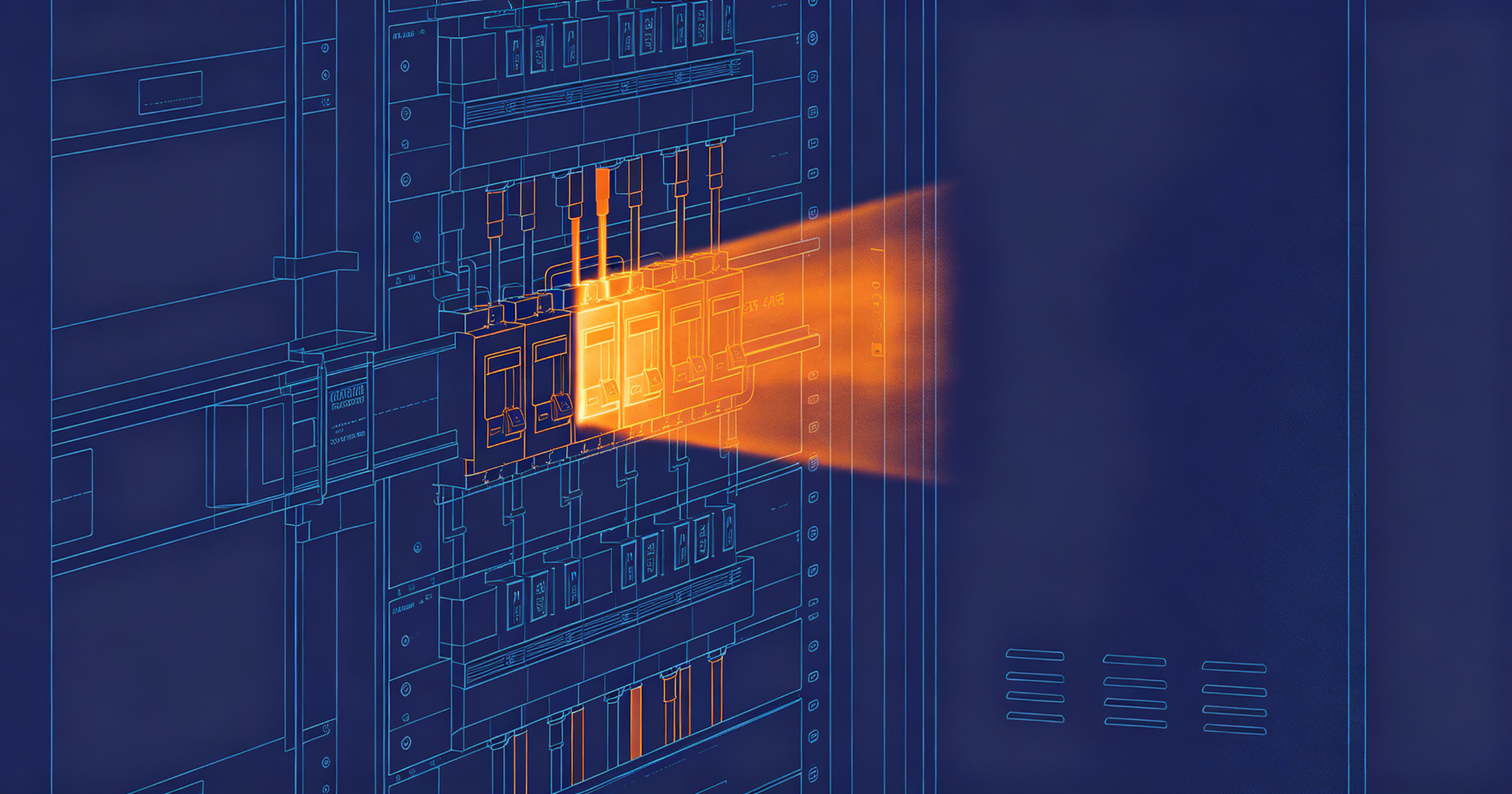
Illustration: How to Detect Electrical Arc Faults Before They Cause Fires
Arc faults rarely announce themselves. They smolder at loose terminals for weeks, carbonizing insulation and pitting conductors, until a single event ignites nearby combustibles. Detection works when you combine scheduled thermographic and insulation testing with continuous monitoring at the point of risk: the panelboard, the junction box, and the equipment feed.
Why Arc Faults Stay Hidden
An arc fault is an unintended discharge across a gap in a circuit. In low-voltage systems (120–480 V AC), a series fault develops in a conductor that has been nicked, crushed, or loosened; a parallel fault jumps between conductors or from conductor to ground. The available fault current may be only 2–30 A — far below the trip threshold of a standard 20 A molded-case breaker. UL 1699 defines the performance requirements for arc-fault circuit interrupters, and its "clearing time" curves show why: a breaker sized for overload protection can carry a 5 A arcing current indefinitely while the arc deposits 1,000 °C or more at the fault point.
That gap between what a breaker protects and what an arc actually draws is the entire detection problem. You close it with periodic measurement and, where justified, continuous monitoring.
NFPA 70B (Recommended Practice for Electrical Equipment Maintenance) treats loose connections and insulation degradation as leading indicators of failure — the same conditions that produce series arcs. Detection is a maintenance discipline, not a single device.
Step 1: Survey the System and Rank the Risk
You cannot test everything every month. Start with a walkdown that produces a ranked list.
- Map every panelboard, disconnect, and motor control center. Record voltage, available fault current, and connected load.
- Flag aluminum branch-circuit terminations, back-stabbed receptacles, and any circuit that has tripped for unknown reasons.
- Mark locations with vibration, moisture, or corrosive atmospheres — pump rooms, cooling towers, food-processing washdown areas.
- Note panels where the load has grown since installation. A 100 A panel now carrying 85 A runs hotter at every termination.
Priority goes to the panels feeding high-occupancy spaces and the equipment you cannot afford to lose. A 2019 study of commercial building fires attributed roughly one in four electrical fires to wiring or related equipment; the distribution is not uniform, so neither should your test schedule be.
Step 2: Perform Thermographic Inspection Under Load
Infrared thermography finds the heat that precedes an arc. It is the fastest first-pass tool you have.
Method
- Scan with the panel energized and carrying at least 40 percent of rated load. At light load, a loose connection may show no temperature rise at all.
- Compare phase-to-phase and phase-to-neutral terminations. A 10 °C differential between phases on identical loads warrants investigation; a 20 °C differential or a reading above 60 °C at the termination is a defect.
- Record ambient temperature and correct for emissivity. Copper bus with oxidized surfaces and painted enclosures have different emissivity values; uncorrected readings can be off by 15 °C or more.
- Inspect the interior with the deadfront removed only under an approved energized-work permit.
Pitfalls
- Scanning from the wrong angle. Reflected heat from a nearby motor or sunlight on a metal enclosure creates false hot spots. Scan perpendicular to the target surface.
- Treating one hot spot as the whole story. Heat migrates along conductors. A hot breaker terminal may be caused by a loose neutral two enclosures away.
- Skipping the neutral bar. Shared-neutral and multiwire branch circuits are a common source of series faults and are routinely ignored during scans.
Thermography tells you where the problem is today. It does not measure insulation condition, and it cannot see an arc that draws too little current to heat the enclosure noticeably. That is why you follow it with insulation testing.
Step 3: Measure Insulation Resistance and Continuity
Insulation resistance (IR) testing finds degradation before it becomes an arc path. Use a megohmmeter rated for the system voltage.
- De-energize and lock out the circuit. Verify absence of voltage at the point of work.
- Disconnect sensitive equipment — VFDs, surge protective devices, electronic controls — before applying test voltage.
- Test at 500 V DC for 300 V and below, 1,000 V DC for 600 V class equipment. Apply for 60 seconds and record the reading at 60 seconds, not at 30.
- Compare phase-to-ground and phase-to-phase. A reading below 1 MΩ on a 480 V circuit is a red flag; below 100 kΩ, repair before re-energizing. IEEE 43 provides the temperature-correction guidance you need to compare readings taken on different days.
- Perform a continuity test across terminations with a low-resistance ohmmeter. A reading above 0.5 Ω on a branch-circuit termination indicates a loose or corroded joint.
Track readings over time. A circuit that reads 500 MΩ this year and 50 MΩ next year is failing, even if 50 MΩ passes a minimum threshold. Trend data catches degradation that a single pass/fail threshold misses.
Step 4: Deploy Continuous Arc Fault Monitoring
Periodic testing covers the day you test. Continuous monitoring covers the other 364.
Arc fault monitoring devices sit at the panelboard or at a critical equipment feed and analyze the current waveform for the high-frequency signature of arcing — broadband noise in the 1–100 kHz range, with characteristic random amplitude modulation. They distinguish arcing from normal switching transients and motor inrush, then alarm or trip before the arc sustains long enough to ignite material.
Two architectures dominate:
- Branch-circuit AFCI devices (UL 1699 listed) installed at the breaker. Effective for 120 V branch circuits in residential and light commercial occupancies; limited current rating and no coverage of feeder or busbar faults.
- Panel-level monitoring systems that watch multiple circuits from one point, combine arc signature analysis with temperature sensing, and report to a building management system. These suit 208–480 V distribution panels where a single fault can take down a floor. Platforms like Chilion's ICOP system provide continuous arc fault and temperature monitoring for low-voltage distribution panels, with alarm thresholds that can be tuned to the specific load profile of each circuit.
Set alarm thresholds conservatively at first. A monitoring system that alarms weekly on normal motor starts gets ignored within a month. Review the first 30 days of data, identify the legitimate transient sources, and adjust.
Step 5: Act on Findings Without Delay
Detection is worthless if the response is a work order that sits for six weeks. Establish a triage rule and follow it.
- Immediate: visible arcing, charring, melted insulation, or a thermographic reading above the equipment's rated temperature. De-energize, isolate, repair, retest.
- Within 72 hours: IR reading below 1 MΩ, termination differential above 20 °C, or repeated arc alarm on the same circuit.
- Next scheduled outage: trending degradation, minor differentials, or single nuisance alarms with an identified benign cause.
After every repair, retest with the same method and instrument used for the original finding. A re-terminated lug that still reads 15 °C above its neighbors has not been fixed — it has been touched.
Common Mistakes That Defeat Detection
- Testing at light load. Thermography and IR testing both lose sensitivity when the circuit is barely loaded. Schedule scans during peak occupancy or production.
- Relying on breakers alone. A standard thermal-magnetic breaker does not detect series arcs. Assuming it will is the most common and most dangerous error.
- Ignoring the neutral. Shared neutrals in multiwire circuits carry unbalanced current and are a frequent arcing site.
- Skipping documentation. Without baseline readings, you cannot distinguish a stable 2 MΩ circuit from a degrading one.
- Setting and forgetting monitoring thresholds. Load profiles change. Re-baseline after any significant addition to the panel.
Need a passive fire protection assessment?
Our editorial team covers enclosure fire suppression, electrical safety monitoring, and fire-resistant coatings. Talk to our partners about your specific application.
Frequently Asked Questions
Can a standard circuit breaker detect an arc fault?
No. A standard thermal-magnetic breaker responds to overload current and short-circuit current, typically well above 100 A for instantaneous trip. A series arc may draw only 2–30 A, below the breaker's thermal trip curve for continuous operation. Only UL 1699 listed AFCI devices or panel-level arc monitoring systems detect the current signature of arcing.
How often should I perform thermographic inspection?
NFPA 70B recommends an annual infrared inspection for most commercial and industrial distribution equipment, with more frequent intervals for critical or heavily loaded panels. Facilities with vibration, moisture, or corrosive exposure should move to semi-annual or quarterly. Any panel that has experienced a fault should be scanned again within 30 days of repair.
What insulation resistance reading indicates a problem?
For 480 V circuits, treat anything below 1 MΩ as a defect requiring investigation and below 100 kΩ as requiring immediate repair before re-energizing. The absolute number matters less than the trend. A circuit that drops by an order of magnitude between annual tests is failing regardless of whether it passes the minimum threshold.
Do arc fault monitoring systems produce false alarms?
Early-generation devices did, mainly from motor starts and dimmer switching. Modern systems use waveform pattern recognition that distinguishes arcing from normal transients, and thresholds are tunable per circuit. Expect a 30-day commissioning period to characterize each circuit's normal signature before relying on alarms for triage decisions.
Detection comes down to three things done consistently: scan under real load, measure insulation condition on a schedule, and monitor the circuits you cannot afford to lose. The tools are mature and the standards — UL 1699, NFPA 70B, IEEE 43 — are specific about what good looks like. What separates a program that prevents fires from one that only documents them is the discipline to act on findings within hours, not quarters, and to keep the trend data that tells you which circuit is next. For related guidance, see panelboard thermal inspection procedures and insulation resistance testing methods. If your facility runs 480 V distribution with limited redundancy, review continuous arc monitoring options before your next outage window.