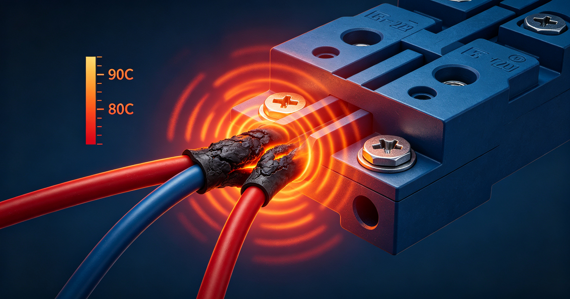
Illustration: The Physics of Electrical Overheating: Why Connections Fail at 70-90C
Electrical connections don't fail because of a single dramatic event. They degrade through a predictable thermal mechanism: contact resistance rises, I²R heating increases, oxidation accelerates, resistance rises further. The 70-90°C band matters because it sits below insulation ratings but above the threshold where aluminum Creep and copper oxide growth become self-sustaining. By the time a connection reaches 90°C, the failure timeline is already set.
Contact Resistance: The Root Cause
Every bolted or crimped connection has a finite contact resistance. On a pristine copper-to-copper joint torqued to specification, that resistance is typically 10-50 microohms. It's not zero because current flows only through microscopic asperities—the actual metal-to-metal contact points where surface irregularities touch. For a typical M10 bolted joint at 400 A, that 25 µΩ produces:
P = I²R = 400² × 25 × 10⁻⁶ = 4 W
Four watts dissipated in a joint with roughly 15 cm² of surface area. The steady-state temperature rise depends on thermal resistance to ambient, but a reasonable estimate for a naturally convecting busbar joint is 15-25°C above ambient at 4 W. In a 40°C switchgear enclosure, that puts the joint at 55-65°C. Not yet in the danger zone—but not far from it.
The problem is that 4 W is not static. Contact resistance increases over time through three mechanisms: oxidation of the base metal, creep relaxation of the joint (which reduces contact pressure), and fretting corrosion from thermal cycling. Each mechanism compounds the others.
Oxidation Kinetics at 70-90°C
Copper oxidation follows a parabolic rate law at moderate temperatures. The oxide film thickness x grows according to:
x² = k·t
where k is the temperature-dependent rate constant following an Arrhenius relationship:
k = k₀·exp(−Ea/RT)
For copper oxidation in air, the activation energy Ea is approximately 0.7-1.0 eV depending on the oxide species (Cu₂O vs. CuO) and humidity. At 50°C, the rate constant is low enough that a properly torqued joint's oxide film stabilizes at a few nanometers—thin enough for tunneling conduction to maintain low resistance. At 80°C, the rate roughly triples. At 90°C, it's 4-5× the 50°C rate.
This matters because copper oxide (Cu₂O and CuO) has a resistivity on the order of 10²-10⁶ Ω·cm depending on stoichiometry—roughly 10¹⁰ to 10¹⁴ times higher than metallic copper. A 100 nm oxide film across a contact asperity effectively insulates it. As more asperities oxidize, the effective contact area shrinks, and resistance climbs.
Aluminum behaves differently but no better. Aluminum oxide (Al₂O₃) is an excellent insulator with a resistivity of ~10¹⁴ Ω·cm. It forms instantly on any exposed aluminum surface. This is why aluminum connections require either abrasion and immediate termination or oxide-penetrating compounds. But even a properly made aluminum connection degrades if temperature exceeds 70-80°C, because the aluminum substrate begins to creep.
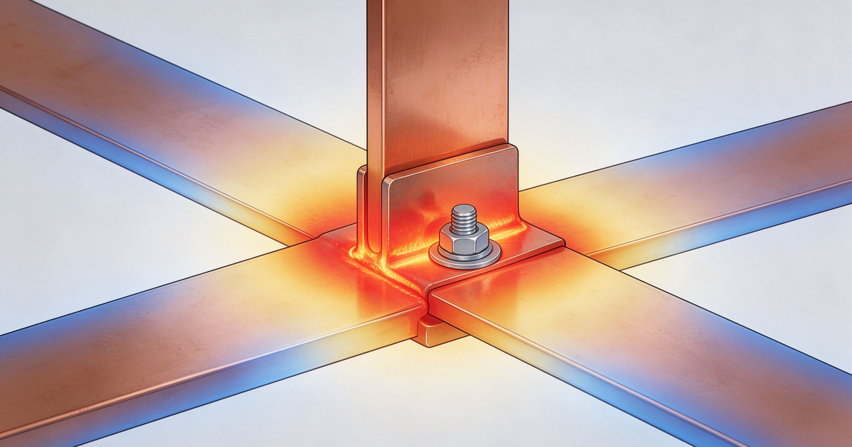
Creep and Stress Relaxation in Aluminum and Copper
Aluminum's melting point is 660°C, and its homologous temperature—the ratio of operating temperature to melting point in Kelvin—determines creep behavior. At 80°C (353 K), aluminum's homologous temperature is 353/933 = 0.38. Above 0.3, creep becomes measurable. Above 0.4, it accelerates.
Bolted aluminum connections lose clamping force over time due to creep. A joint torqued to 40 N·m at installation may retain only 25 N·m after 5 years at 80°C. Reduced clamping force means reduced contact pressure, which increases contact resistance, which increases temperature, which accelerates creep. This is the thermal-electrical feedback loop that drives runaway failure.
Copper's melting point is 1085°C (1358 K). At 90°C (363 K), its homologous temperature is 0.27—below the creep threshold for most copper alloys. Copper connections are less prone to creep-induced loosening, but they're not immune. Brass terminals and tin-plated copper can creep at 90°C, particularly under high contact pressure where dislocation motion is thermally activated.
ASTM B545 and UL 486A/B specify temperature-rise limits for electrical connections: 30°C rise above a 40°C ambient for most terminations, which yields a maximum operating temperature of 70°C. Connections operating at 80-90°C are already outside the design basis.
Thermal Runaway: When 70°C Becomes 200°C
The transition from elevated temperature to failure is nonlinear. Consider a joint with initial resistance R₀ = 25 µΩ at 20°C. Copper's temperature coefficient of resistance is 0.00393/°C. At 80°C, resistance becomes:
R₈₀ = R₀ × [1 + α(T − T₀)] = 25 × [1 + 0.00393 × 60] = 25 × 1.236 = 30.9 µΩ
That's a 24% increase from temperature alone. But add oxide growth over 5 years—say the effective contact area halves—and resistance doubles to ~62 µΩ. At 400 A, that's now 9.9 W instead of 4 W. Higher power dissipation raises temperature further, which accelerates oxidation, which raises resistance again.
The system reaches a tipping point when the heat generation rate exceeds the heat dissipation capacity of the connection's thermal path. For a joint in still air, natural convection and radiation can typically dissipate 5-10 W before temperature exceeds 100°C. Once past that, the joint enters thermal runaway: temperature climbs until the conductor melts, the insulation ignites, or the joint fails mechanically.
This is why infrared thermography surveys flag connections above 70°C as "priority" and above 90°C as "critical." NFPA 70B (Recommended Practice for Electrical Equipment Maintenance) Table 11.2.2 classifies temperature differentials: a 15-30°C rise above a reference component warrants investigation; above 30°C requires immediate action. In a 40°C ambient, a 90°C connection is a 50°C differential—well into the "major discrepancy" category.
Material-Specific Failure Modes
Aluminum Connections
Aluminum's creep problem is compounded by its oxide. Once clamping force drops below the threshold needed to fracture the oxide layer at asperity contacts, resistance climbs rapidly. This is why aluminum-to-copper transitions require bimetallic connectors or antioxidant compound. Without them, galvanic corrosion at the interface adds resistance and generates localized heating.
Copper Connections
Copper's failure mode is primarily oxide-driven. At 90°C, copper oxide growth follows a logarithmic-to-parabolic transition. The initial film (Cu₂O) is a semiconductor with a bandgap of ~2.1 eV. As it thickens beyond 10 nm, electron tunneling becomes negligible, and resistance rises sharply. Tin-plated copper delays this because tin oxide (SnO₂) is conductive, but tin's melting point is 232°C—above the danger zone but not by much if hotspots form.
Compression Lugs and Crimps
Crimped connections rely on cold welding between the conductor strands and the lug barrel. At 80-90°C, stress relaxation in the copper or aluminum barrel reduces contact pressure. For aluminum compression lugs, this is particularly problematic: the aluminum barrel and aluminum conductor both creep, and the joint loosens. IEEE Std 837 (Qualifying Permanent Connections Used in Substation Grounding) requires connections to withstand 350°C without exceeding specified resistance limits—but that's a short-time withstand, not continuous operation.
Detection and Mitigation
The practical takeaway for facility engineers: 70°C is the first warning, 90°C is the last. Between those temperatures, you have a window—months to years depending on load profile and environment—to intervene before failure. Infrared surveys at load, torque verification, and resistance measurements (micro-ohmmeter readings across joints) are the standard tools.
Real-time monitoring systems like Chilion's ICOP are increasingly specified in data centers and industrial plants where continuous thermal surveillance of busbar joints and switchgear terminations supplements periodic IR scans. The physics doesn't change, but the detection timeline does.
Mitigation follows directly from the failure mechanisms. Reduce temperature by increasing conductor size or improving ventilation. Reduce resistance by re-torquing to specification (and using Belleville washers to maintain clamping force). For aluminum, use oxide-penetrating compound and bimetallic transitions. For copper, ensure plating integrity and avoid dissimilar metal junctions without proper isolation.
The 70-90°C band is not arbitrary. It's the temperature range where oxidation kinetics, creep rates, and thermal runaway converge. A connection at 65°C may last 20 years. The same connection at 85°C may fail in 3. The difference is not linear—it's exponential, and it's driven by the physics of contact resistance, oxide growth, and heat transfer.
Need a passive fire protection assessment?
Our editorial team covers enclosure fire suppression, electrical safety monitoring, and fire-resistant coatings. Talk to our partners about your specific application.
Frequently Asked Questions
Why is 70°C specifically the threshold for concern?
70°C represents the point where copper oxidation rates become significant enough to measurably increase contact resistance over months, and where aluminum creep begins to reduce clamping force in bolted connections. UL 486A/B and IEC 60947-1 specify maximum terminal temperatures of 70°C for most terminations under continuous load, so operation above this value means the connection is outside its design envelope.
Can a connection at 90°C fail immediately?
Not immediately, but the failure timeline accelerates sharply. At 90°C, copper oxide growth is roughly 4-5× faster than at 50°C, and aluminum creep rates increase by an order of magnitude. A connection that would last 20 years at 60°C may fail in 1-3 years at 90°C. Thermal runaway can occur within hours if resistance rises enough to push power dissipation beyond the joint's heat dissipation capacity.
Does torque matter more than conductor size?
Both matter, but torque directly controls contact resistance. A conductor sized for 400 A will still overheat if the termination is torqued to 50% of specification—contact resistance rises, I²R heating increases, and temperature climbs. Re-torquing to manufacturer specification (typically 40-70 N·m for M10 hardware) is the single most effective mitigation for connections already in the 70-90°C range.
How do I measure connection temperature without infrared?
Micro-ohmmeter measurements across the joint provide a resistance proxy: a reading above 50 µΩ for a bolted busbar joint indicates degradation. For continuous monitoring, bolt-on thermocouples or fiber-optic sensors on busbar joints give real-time temperature data. NFPA 70B recommends a baseline resistance measurement at commissioning, with periodic comparisons to detect upward trends before temperatures reach critical levels.