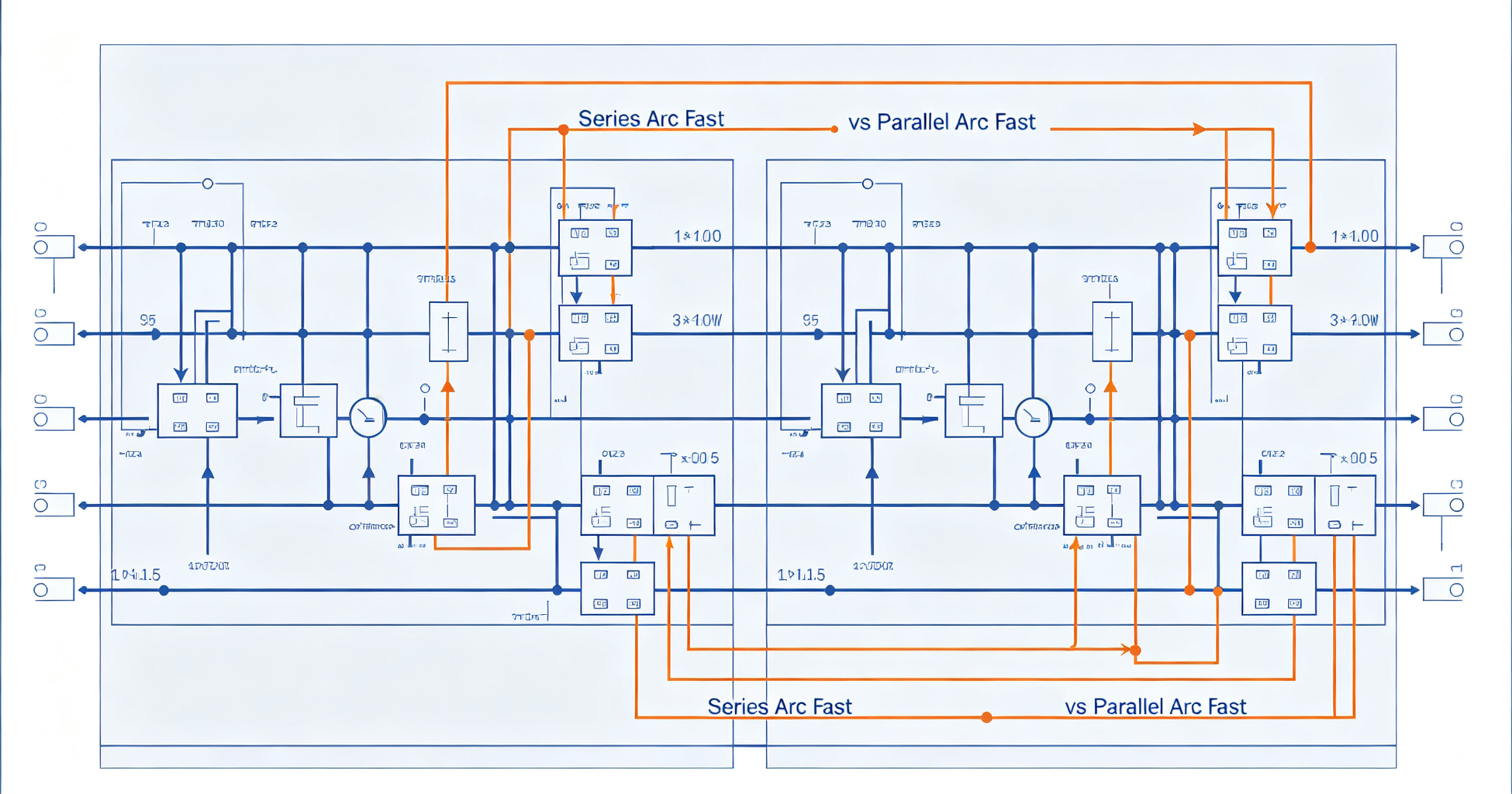
Illustration: Understanding Series Arc vs Parallel Arc Fault Detection in Low-Voltage Panels
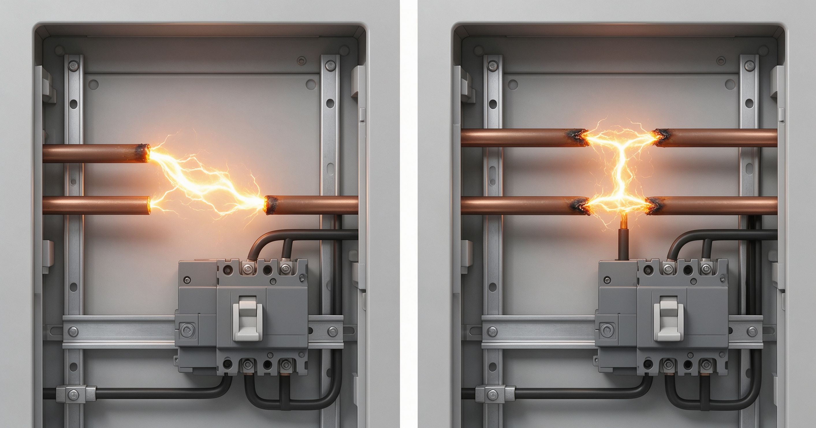
A series arc flows through one conductor and is limited by the load, while a parallel arc bridges two conductors and draws current limited mainly by the source impedance. That distinction dictates how each fault behaves, why detection thresholds differ, and why a single sensing method rarely covers both.
Low-voltage panels — 120/240 V split-phase in North America, 230/400 V in Europe — are the last line of defense before branch circuits disappear into walls and conduits. Once conductors leave the enclosure, they are largely inaccessible, and any arcing that develops beyond that point must be found by the protective devices installed at the source. Understanding how series and parallel arcs differ is the first step toward specifying detection that actually works.
Definitions and Physical Behavior
An arc is a sustained electrical discharge through ionized gas. In low-voltage systems, arcs form when conductors separate under load, when insulation carbonizes and creates a conductive path, or when a loose terminal develops high contact resistance that heats adjacent material until it breaks down.
The two categories are defined by topology, not by cause:
- Series arc: occurs in a single conductor that has been severed, loosened, or partially broken. The arc sits in series with the load, so the current through it is the load current — typically a few amperes to perhaps 20 A on a 15 A or 20 A branch circuit.
- Parallel arc: occurs between two conductors at different potentials (line-to-neutral, line-to-ground, or line-to-line). The arc current bypasses the load entirely and is limited only by the impedance of the fault path and the transformer feeding the panel. Available fault current can reach thousands of amperes before the upstream breaker trips.
A useful analogy: a series arc is like a kink in a garden hose — flow continues, but the restriction generates heat at one point. A parallel arc is a hole punched through the hose wall into a second hose — most of the water takes the new path, and the flow rate is limited only by supply pressure.
Why Current Magnitude Is Not a Reliable Discriminator
The most common misconception is that parallel arcs always draw high current and series arcs always draw low current. That is true at the instant of fault, but not over the arc's lifetime.
A parallel arc can start as a high-resistance carbonized path drawing only a few amperes. As the path heats, resistance drops, current rises, and the arc can escalate to a bolted-fault magnitude within seconds. Conversely, a series arc on a heavily loaded circuit can pass 16 A continuously while generating localized temperatures above 1,000 °C at the arc root — hot enough to ignite adjacent PVC insulation, which has an ignition temperature in the 390–450 °C range.
Current magnitude tells you what the arc is doing right now. It does not tell you what it will do in ten seconds, or whether the heat it produces will reach ignition temperature before the breaker reacts.
This is why arc fault detection cannot rely on overcurrent thresholds alone. A 20 A circuit breaker will not trip on a 12 A series arc, no matter how long it burns.
Detection Physics: What the Sensor Actually Sees
Series arc signatures
Series arcs produce a distinctive current waveform: a series of high-frequency bursts (typically 1–100 kHz) superimposed on the fundamental 50/60 Hz sine wave, with shoulders and plateaus where the arc extinguishes and restrikes each half-cycle. The broadband noise is generated by the rapid ionization and deionization of the gap.
Because the arc is in series with the load, the current signature is present on the same conductor regardless of where in the circuit the fault occurs. A current transformer at the panel can detect it — but it must distinguish arc noise from the switching noise of dimmers, variable-speed drives, and switched-mode power supplies, which produce similar high-frequency content.
Parallel arc signatures
Parallel arcs generate much larger current steps, often with a sharp leading edge and a broadband burst that couples into adjacent conductors capacitively. The signature appears on multiple circuits simultaneously if the fault is line-to-ground. Detection is often easier in magnitude terms but harder in discrimination terms, because a parallel arc can look like a motor start or an inrush event to a simple threshold detector.
UL 1699, the standard covering arc-fault circuit interrupters in North America, defines separate test protocols for series and parallel arcs, including the carbonized cable test and the masked arc test. Devices must clear both within specified times — typically 1 second for parallel arcs above 75 A and up to 5 seconds for series arcs at lower currents.
Where Each Fault Typically Originates in a Panel
Panel-level faults are not evenly distributed. Field data and forensic analysis point to specific locations:
- Loose terminals on breakers and neutral bars. These produce series arcs. A terminal torqued to 20 in-lb instead of the specified 35 in-lb can develop enough resistance to heat cyclically, loosen further, and eventually arc.
- Damaged insulation on branch conductors at the panel entry. Nicked insulation from a knockout or a staple produces a parallel arc path to the enclosure if the conductor contacts the metal.
- Vermin damage and UV-degraded insulation downstream of the panel. Rodents chew through insulation, creating line-to-neutral parallel arcs. These are the faults that traditional thermal-magnetic breakers miss entirely until ignition.
- Failed splices and backstabbed receptacles. Both create series arcs. The 2017 and 2020 NEC expansions of AFCI requirements (Articles 210.12 and 406.4(D)(4)) target exactly these failure modes.
Early warning solutions such as Chilion's ICOP can detect developing faults before they reach ignition temperatures, which matters because a parallel arc can escalate from a few amperes to a bolted fault in under two seconds.
Why Detection Algorithms Must Handle Both
A detector tuned only for series arcs will miss the high-current signature of a parallel fault if it uses a narrow frequency band that saturates. A detector tuned only for parallel arcs will trip nuisance on motor starts and will miss the low-level series arc that poses the greater long-term ignition risk.
Modern AFCI and AFDD devices use a combination of:
- High-frequency current sensing (typically 1–20 MHz bandwidth) to capture arc noise
- Fundamental current measurement to establish load context
- Time-domain analysis of the current waveform to identify the shoulders and restrikes characteristic of series arcs
- Pattern recognition or machine learning to distinguish arc signatures from known nuisance sources
IEC 62606, the international standard for arc fault detection devices, requires testing with both series and parallel arc generators, including a carbonized cable test and a point-contact test. Devices certified to IEC 62606 are rated for 230/400 V systems and must not trip on inrush currents up to 10 times rated current for specified durations.
Practical Implications for Panel Design and Maintenance
Specifying detection is only half the task. The other half is ensuring the panel itself does not create the conditions for either fault type.
- Torque all terminations to manufacturer specification and re-torque after the first thermal cycle. Aluminum conductors require particular attention because of creep.
- Use torque-marking compounds or calibrated drivers. A 2022 study of residential panels found that more than 30% of field-terminated connections were below specified torque.
- Maintain conductor bend radius at panel entries. Sharp bends stress insulation and create the mechanical damage that becomes a parallel arc years later.
- Separate line and neutral conductors where possible. Physical separation reduces the chance of a line-to-neutral parallel arc forming across a damaged insulation boundary.
- Verify AFCI/AFDD function at commissioning and at each maintenance interval. Test buttons verify the trip mechanism, not the sensing algorithm.
The distinction between series and parallel arcs is not academic. It determines where you place sensors, what thresholds you set, and how you interpret the data those sensors produce. A panel that detects only one type is a panel that misses half the risk.
Need a passive fire protection assessment?
Our editorial team covers enclosure fire suppression, electrical safety monitoring, and fire-resistant coatings. Talk to our partners about your specific application.
Frequently Asked Questions
Can a standard circuit breaker detect a series arc?
No. A series arc draws only the load current, which is below the breaker's thermal-magnetic trip threshold. A 15 A breaker on a 12 A series arc will not trip regardless of how long the arc persists. Detection requires high-frequency current sensing and waveform analysis, which is what AFCI and AFDD devices provide.
What is the difference between UL 1699 and IEC 62606?
UL 1699 covers arc-fault circuit interrupters for North American 120/240 V systems and specifies tests including the carbonized cable and masked arc tests. IEC 62606 covers arc fault detection devices for 230/400 V systems and includes similar but not identical test protocols. Devices are typically certified to one standard or the other, not both.
Why do parallel arcs sometimes trip a breaker on their own?
A parallel arc can escalate to a bolted fault current that exceeds the breaker's instantaneous trip threshold. At that point the magnetic element trips in under one cycle. The problem is the window between arc initiation and escalation — often two seconds or more — during which the arc can ignite nearby material.
How often should AFCI devices be tested in a commercial panel?
Manufacturers typically recommend monthly test-button operation and annual verification of sensing function. Test buttons confirm the trip mechanism, not the arc detection algorithm. For critical facilities, annual testing with a calibrated arc generator provides a more complete verification of detection performance.