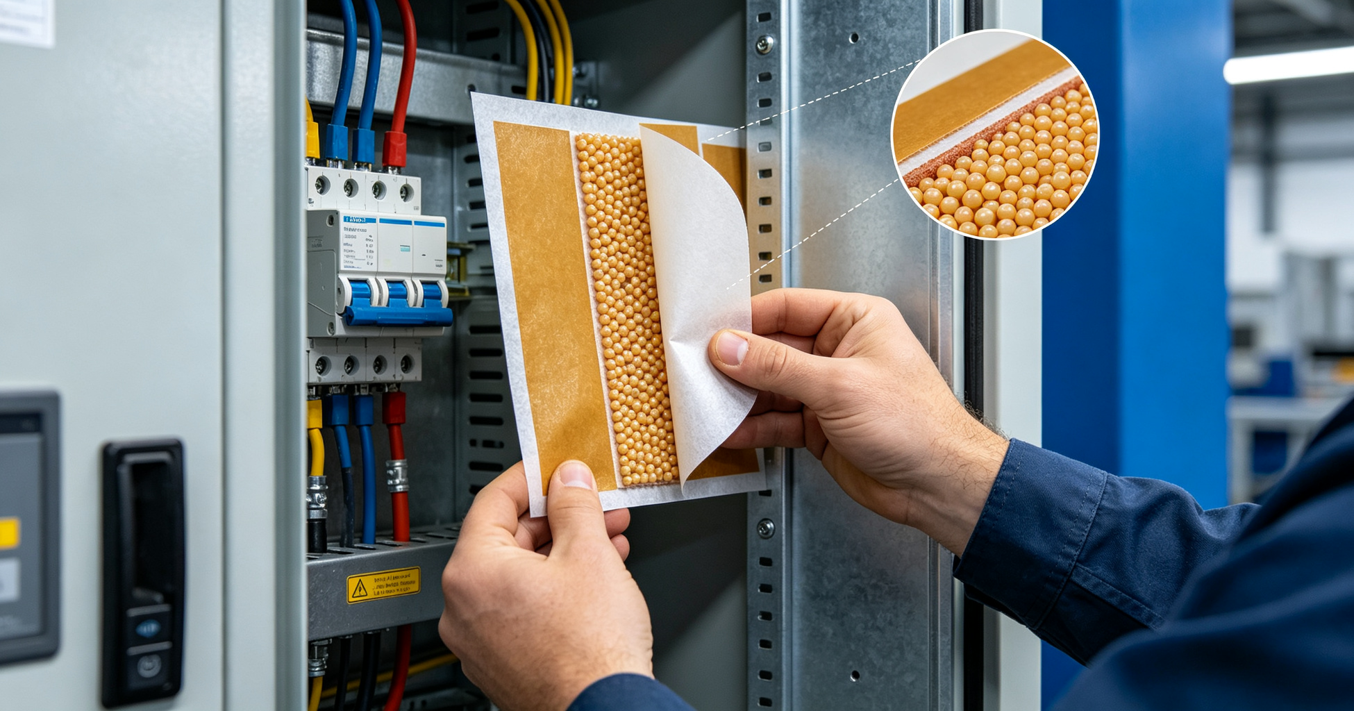
A 480 V motor control center that tripped twice in one month after an arc inside the enclosure, before a passive patch was added.
A 480 V motor control center in a food processing plant tripped offline twice in one month after arc faults ignited inside the enclosure. The facility manager wanted a passive suppression layer that would activate without power, without piping, and without a control panel. Microencapsulated fire patches solved the problem: self-adhesive pads that rupture at a set temperature and release an extinguishing agent directly onto the ignition source. Installation takes 20 to 40 minutes per enclosure and requires no special certification beyond standard lockout/tagout procedures.
What Microencapsulated Fire Patches Actually Do
Each patch contains thousands of microscopic capsules filled with a clean extinguishing agent, typically a fluoroketone or a dry chemical blend. The capsule shell is engineered to rupture at a specific activation temperature, usually between 110 °C and 180 °C (230 °F to 356 °F), depending on the formulation. When an arc, overloaded terminal, or failed component generates enough heat, the nearest capsules burst and release agent within centimeters of the fault.
This is fundamentally different from a total-flooding system. You are not protecting the volume of the enclosure. You are protecting the specific points where ignition is most likely: terminals, busbars, contactors, and cable entries. That distinction drives every installation decision that follows.
Relevant standards to reference during specification include NFPA 2010 (Standard for Fixed Aerosol Fire-Extinguishing Systems) for the agent delivery principle, UL 94 for the flammability rating of the adhesive backing, and IEC 60529 for the enclosure ingress protection rating you must maintain after installation. Firequell's microencapsulated patches represent one commercially available implementation of this technology, and their datasheets list activation temperature and coverage area per unit, which you will need for the layout step.
Tools and Materials You Will Need
- Microencapsulated fire patches (sized to enclosure; typical coverage is 0.1 to 0.2 m² per patch)
- Isopropyl alcohol (99% concentration) and lint-free wipes
- Infrared thermometer or thermocouple probe
- Torque screwdriver or wrench set matched to terminal hardware
- Heat gun (variable temperature, capable of 60–80 °C)
- Digital multimeter with clamp attachment
- Camera or phone for pre-installation documentation
- Lockout/tagout kit
- Personal protective equipment: arc-rated face shield, voltage-rated gloves, flame-resistant clothing
Do not substitute a general-purpose adhesive promoter for the surface prep step. Most patch manufacturers specify isopropyl alcohol only. Acetone and other solvents can leave residues that degrade the pressure-sensitive adhesive over time.
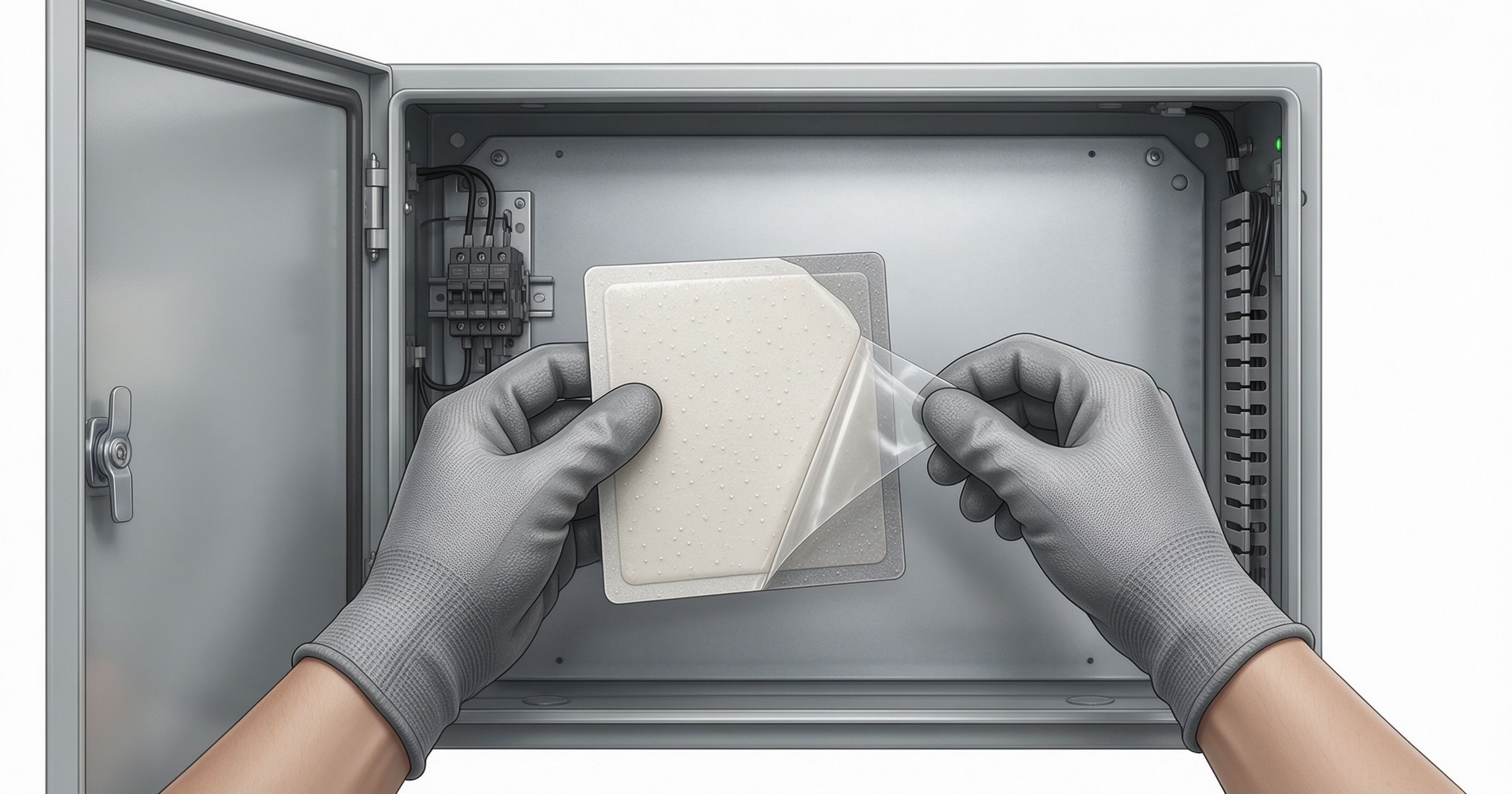
Step-by-Step Installation Procedure
Step 1: De-energize and Verify
Follow your site's lockout/tagout procedure. Test for absence of voltage at all phases and at the neutral, using a meter rated for the enclosure's voltage class. Wait the full discharge time specified for any capacitors or VFDs in the enclosure. Document the verification with a photo before you touch anything else.
Step 2: Inspect and Document the Interior
Open the enclosure and photograph the interior layout. Identify the three to five highest-risk ignition points. These are almost always:
- Line-side and load-side terminals of the main breaker or disconnect
- Busbar joints and bolted connections
- Contactor and relay coil terminals
- Cable lug terminations
- Any component with a history of overheating or discoloration
Use the infrared thermometer to record baseline temperatures at these points under normal load. A terminal running 15 °C above ambient with no load variation is a candidate for closer patch placement.
Step 3: Clean the Mounting Surfaces
Wipe each mounting surface with isopropyl alcohol and a lint-free cloth. Allow 60 seconds to flash off. The surface must be dry, free of oil, dust, and oxidation. On painted enclosure interiors, check that the paint is fully cured. Fresh powder coat can outgas and lift the adhesive within weeks.
Do not mount patches on surfaces that exceed 60 °C (140 °F) during normal operation. Sustained heat above that threshold degrades the adhesive and can cause the patch to release before activation temperature is reached.
Step 4: Plan the Layout
Position each patch so its active face points toward the ignition point, with a clearance of 25 to 50 mm (1 to 2 inches) from live conductors. You are aiming for line-of-sight between the capsule surface and the fault location. Do not wrap patches around busbars or place them in direct contact with energized metal.
For a typical 600 mm × 400 mm × 250 mm enclosure, three patches are usually sufficient: one above the main breaker terminals, one adjacent to the busbar joint, and one near the cable entry. Larger enclosures or those with multiple compartments may need six or more. Check the manufacturer's coverage rating rather than guessing.
Step 5: Apply the Patches
- Peel the release liner from one corner only.
- Align the patch with your planned position.
- Press the exposed corner firmly to the surface.
- Slowly peel the remaining liner while pressing the patch down with a roller or your thumb.
- Apply firm pressure across the entire patch for 15 seconds, working from center to edges.
If the ambient temperature inside the enclosure is below 15 °C (59 °F), warm the mounting surface with a heat gun set to 60–80 °C for 10 to 15 seconds before applying. Cold surfaces prevent the adhesive from wetting out properly.
Step 6: Verify Adhesion and Clearance
After 10 minutes, attempt to lift one corner of each patch with light finger pressure. It should resist. Check that no patch interferes with door closure, moving parts, or ventilation paths. Confirm minimum clearances to live parts per the applicable IEC 61439 or UL 508A spacing tables.
Step 7: Restore Power and Document
Close the enclosure, remove lockout/tagout, and restore power. Log the installation date, patch part number, activation temperature, quantity, and locations on the enclosure's maintenance record. Most manufacturers recommend visual inspection every 12 months and replacement every 5 to 7 years, or sooner if the patches show discoloration, lifting, or physical damage.
Common Pitfalls to Avoid
- Mounting too far from the fault. A patch 300 mm from a terminal may not rupture before the fault spreads. Keep the distance under 100 mm where possible.
- Covering ventilation openings. Blocking airflow raises internal temperatures and can trigger premature activation.
- Ignoring the enclosure's IP rating. If the enclosure is rated IP54 or higher, verify that the patch and its adhesive do not compromise the gasket seal.
- Using patches as a substitute for proper overcurrent protection. These devices mitigate the consequences of a fault. They do not prevent one.
- Skipping the baseline temperature survey. Without it, you cannot tell whether a patch activated from a real fault or from chronic overheating.
For related guidance on enclosure protection strategy, see arc flash boundary calculation and thermal imaging of electrical panels. If you are working with hazardous location enclosures, review ATEX and IECEx enclosure requirements before specifying any internal device.
Need a passive fire protection assessment?
Our editorial team covers enclosure fire suppression, electrical safety monitoring, and fire-resistant coatings. Talk to our partners about your specific application.
Frequently Asked Questions
At what temperature do microencapsulated fire patches activate?
Most formulations rupture between 110 °C and 180 °C (230 °F to 356 °F). The exact threshold depends on the capsule shell composition and is listed on the manufacturer's datasheet. Choose a patch whose activation temperature sits at least 30 °C above the highest normal operating temperature measured inside the enclosure.
Can I install fire patches in an enclosure that is already energized?
No. De-energize and verify absence of voltage before opening any enclosure. Even though the patches themselves are passive, installation requires physical access to terminals and busbars. Follow NFPA 70E or your regional equivalent for arc-rated PPE and lockout/tagout.
How often should fire patches be replaced?
Plan on replacement every 5 to 7 years, or per the manufacturer's shelf-life and in-service guidance. Inspect annually for lifting edges, discoloration, or physical damage. Any patch that has activated must be replaced immediately, and the cause of activation investigated before returning the enclosure to service.
Do fire patches replace a clean agent suppression system?
No. They supplement, not replace, total-flooding or compartment-specific systems. Patches address localized ignition at known hot spots. A clean agent system protects the entire enclosure volume. For critical infrastructure, specify both and document how they interact during a fault event.